11.5.21 – EC&M
Knowing the ins and outs of this technology can help you seize new opportunities.
As an electrician, there’s no doubt you’re hearing a lot about Power over Ethernet (PoE) as a means of delivering low-voltage DC power over network cabling to LED lights. With 90% growth expected in the next 10 years from PoE lighting alone — and many jurisdictions allowing installation of these systems by low-voltage contractors rather than licensed electricians — you need to get out in front of this technology. To take full advantage of the opportunity and ensure that your PoE lighting installations go smoothly, however, you need to understand how PoE works, the various standards and classifications, performance parameters, and how best to test and troubleshoot these systems.
How does PoE work?
You probably already know how DC power works. You’re also probably familiar with implementing AC-to-DC conversion technology to distribute DC power to LED lights and other DC-powered devices. PoE is a bit different in that it eliminates the need for any AC power or conversion, delivering DC power directly over the same cable used to connect devices in an IT network, such as Category 5E, 6, or 6A balanced twisted-pair cables. Unlike unintelligent non-networked DC-powered devices, PoE devices also transmit data, such as control information for lighting systems (i.e., luminosity, color temperature, etc.) or a video signal for a surveillance camera.
In a PoE circuit, DC power is delivered to a powered device (PD) such as an LED luminaire from power sourcing equipment (PSE). This is typically a PoE-enabled Ethernet network switch located in an IT telecom room. For customers that have non-PoE switches, power can be delivered using a PoE injector that sits between the switch and the device.
Regardless of the type of PSE, power is delivered by the PSE only after it is requested by the PD. If the PD is disconnected, then the PSE will remove power. This is referred to as a PoE handshake. It works by the PSE sending out detection signals to determine if a PD is connected and then supplying the amount of power requested by the PD. This handshake ensures non-PoE devices on the network do not receive DC power that could damage sensitive electronics. In addition, it improves safety over other power delivery methods that always have power flowing, regardless of whether a device is connected. It’s important to note that with PoE, the voltages are only in the range of 43VDC to 57VDC and are therefore considered to be safety extra-low voltage (SELV).
PoE power can be delivered differently depending on the power level and type of PoE being used, which is defined by its IEEE standard. The first PoE standard introduced in 2003 was the IEEE 802.3af standard, referred to as Type 1, which delivers a maximum of 15.4W (13W available at the device). This was followed by IEEE 802.3at Type 2 (sometimes referred to as PoE+) in 2009, which delivers maximum power to 30W (25.5W available at the device).
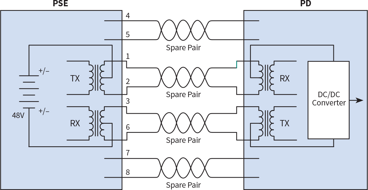
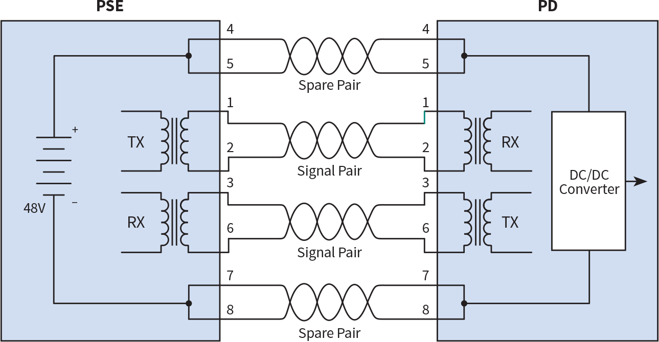
Both Type 1 and Type 2 PoE deliver power over just two pairs of a four-pair cable using one of two methods — Alternative A and Alternative B. As shown in Fig. 1a and Fig. 1b, Alternative A power is delivered simultaneously with data over pairs 1-2 and 3-6, while Alternative B is delivered over spare pairs 4-5 and 7-8. Alternative B is only compatible with lower-speed systems that only require two pairs for sending data, while Alternative A is compatible with both two-pair and four-pair data systems.
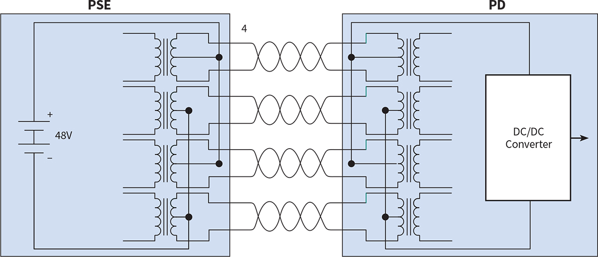
In 2018, IEEE introduced the 802.3bt standard that delivers power across all four pairs simultaneously with data to provide more power. Referred to as four-pair PoE (4PPoE) and sometimes denoted as PoE++, this standard includes Type 3 that delivers a maximum of 60W (51W available at the device) and Type 4 that delivers a maximum of 90W (71.3W available at the device), as shown in Fig 2.
Before the IEEE 802.3bt standard, switch manufacturer Cisco introduced a proprietary four-pair PoE technology referred to as Universal PoE (UPoE) that was able to deliver a maximum of 60W. Cisco UPoE is now capable of delivering 90W of PoE and is in complete compliance with 802.3bt standards. Thus, the term UPoE is often used interchangeably with 4PPoE or PoE++.
Regardless of which type of PoE is being used, DC power is transmitted over the pairs by applying common-mode voltage, meaning that the current is split evenly between each pair and between the two conductors of a pair.
Defining PoE classes
IEEE PoE standards and types encompass a wide range of power. For example, while Type 1 delivers a maximum power of 15.4W with 13W available at the device, some devices may only need 7W of power or less. To further define the power levels, PoE is divided into eight classes ranging from Class 1 with just 4W delivered, to Class 8 with the maximum 90W delivered as shown in the Table, which demonstrates the IEEE standards and the various classes within those standards.

To facilitate implementation, the Ethernet Alliance developed a PoE certification program for easily identifying PSEs and PDs by class to determine compatibility. This program tests and certifies products with a simple marking system that shows the class for PSE and PD (Fig. 3). If the label on the PSE indicates a class that is equal to or higher than the PD, they are compatible.

Another reason for classification is to allow power requirements to be negotiated for better management of the PSE’s total power budget. For example, if the PSE is Class 6, but the PD is only Class 5, the PSE can match the requirements of the device rather than putting out more power than is required.
Potential PoE pitfalls
In low-voltage twisted-pair cabling for networks, there are a variety of performance parameters defined by industry standards that need to be considered because they can impact data transmission, such as length, attenuation, crosstalk, and return loss. Network cable plants are tested for compliance to industry standards for certification, which typically is required to achieve a vendor warranty from the cabling system manufacturer. When it comes to PoE, there are additional performance parameters to consider.
As previously mentioned, PoE is delivered via a common-mode split between pairs and between conductors of a pair. For this power split to happen, the DC resistance between two conductors in a pair and the DC resistance between pairs must be balanced. If DC resistance is not balanced, it can cause PoE to malfunction and distort the data signals transmitting on the same pairs. Industry standards specify the maximum DC resistance unbalance within a pair and from pair-to-pair.
It’s important not to confuse DC loop resistance and DC resistance unbalance. Measured in ohms (Ω), DC loop resistance is the sum of the DC resistance of two conductors in a pair looped at one end of the link, rather than the difference (Fig. 4).

In addition to DC resistance unbalance, bundles of network cables delivering PoE can experience heat rise with the cables, especially those in or near the middle of a bundle, with no way to dissipate the heat. When the temperature within network cables increases, signal loss (i.e. attenuation) also increases. In network cabling, this signal loss is referred to as insertion loss. Just like in AC electrical systems, the higher the power level and smaller the cable gauge, the more the cables heat up.
Heat rise within bundles of cables carrying PoE can especially be of concern in higher temperature environments such as above the ceiling in hot climates. Because heat rise can cause signal loss, it can prevent proper data transmission and prevent PoE devices from functioning. To address the issue, the National Electric Code (NEC) requires that Class 2 and Class 3 circuits carrying more than 60W of power comply with bundling requirements. Section 725.144 of the NEC includes ampacity tables for four-pair cables that provide recommended bundle sizes based on the temperature rating and gauge of the cable, as well as the ampacity (current expressed in amperes) carried by each conductor in the cable.
Using the ampacity tables can be avoided by not bundling cables during installation or through the use of Class 2 or Class 3 LP-rated cables that are listed by UL as suitable for carrying power and data circuits up to their marked ampere limit for each conductor without exceeding the temperature rating of the cable. If LP-rated cables and avoiding bundles are not an option, it is recommended to keep bundle sizes to 24 cables. In bundles of 24, cables that are 24 AWG or larger with a minimum operating temperature of 60°C (i.e., typical for most category twisted-pair network cables) will not cause an issue in most installations.
How to test and troubleshoot PoE
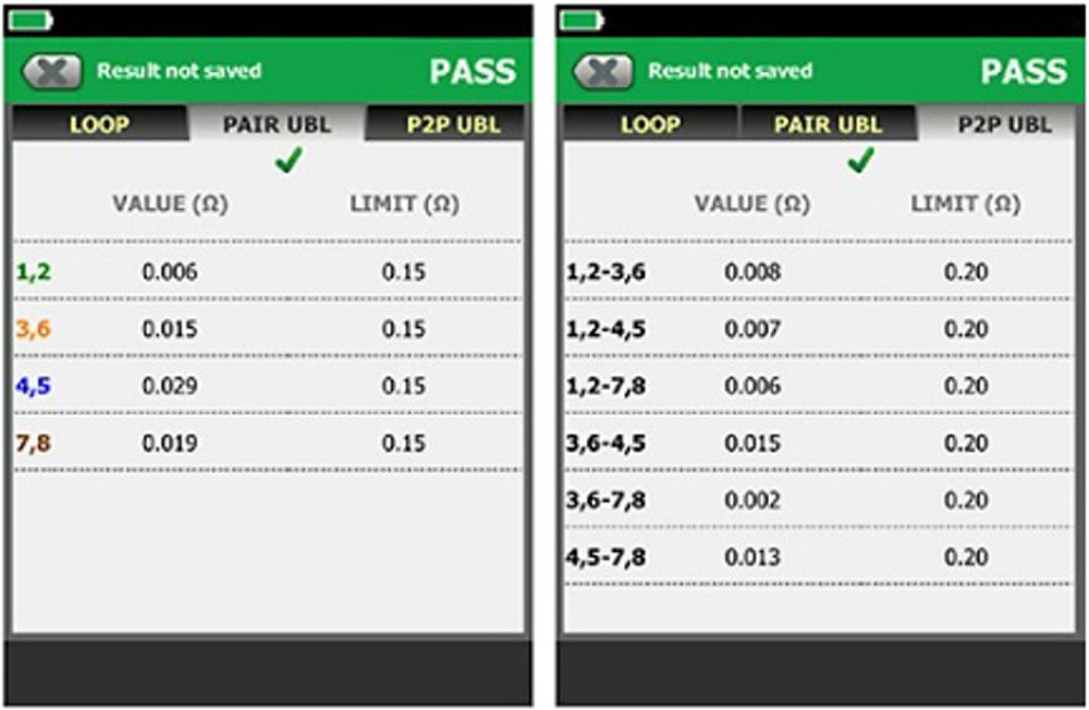
In AC power systems, you’re familiar with voltage drop calculations and measuring voltage with a digital multimeter. The first recommendation for testing PoE systems is to field test the cabling for DC resistance unbalance. While vendors may specify a DC resistance unbalance value on their cable, field testing is recommended. This is because it is often caused by poor workmanship, such as exceeding maximum bend radius, not maintaining pair twists as close to the point of termination as possible, or not terminating each conductor consistently. Fortunately, there are cable testers on the market that enable testing for DC resistance unbalance along with other important data performance parameters. The tester screens in Fig. 5 show testing results for DC resistance unbalance on individual pairs (PAIR UBL) and between pairs (P2P UBL). Note that these tests are not part of the standard Category cable field tests and should be specified and enabled in addition to those tests. This additional testing adds a negligible amount of time to a standard Category test.
If you need to troubleshoot the system once the actual PSE is up and running, you will want to check the class to make sure that the class of the PSE is equal to or higher than that of the PD. An easy way to accomplish this is with a network tester that, when connected to the PSE, can display the class (1-8) of power available on the link. That information can then be compared to the specifications of the PD.
The final option for troubleshooting is PoE load testing, which involves acquiring real-time information about the actual amount of power at the PD. If there is a problem with the PSE (such as incorrect configuration or too many devices requesting too much power), or excessive loss along the length of the cable, then the amount of power may not match the class of power required by the PD.
To conduct PoE load testing, you need a tester that can communicate with the PSE. These testers then place a load on the connection and measure exactly how much power is being delivered.
While you may be new to PoE, it doesn’t have to be complicated. With the right tools, equipment, and training, you can add this type of work to your service offering and compete with low-voltage specialty contractors.
Mark Mullins currently oversees Fluke Network’s Global Communications efforts. As a member of the Ethernet Alliance Marketing Committee, he is responsible for promoting the Gen 2 Power over Ethernet Certification program. He can be reached at mark.mullins@flukenetworks.com.
